Obstacle Avoidance
In this blog, we demonstrate how to run our obstacle avoidance algorithm using raspberry pi and a Sphero RVR rover. The primary goal is to explore its surroundings while detecting and avoiding obstacles. This algorithm uses Obstacle Detection algorithm to identify obstacles. For more details, you can check out the Previous Blog.
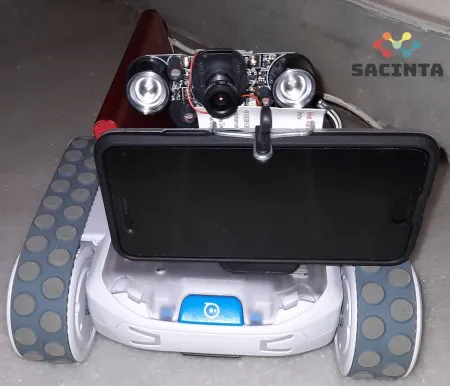
The Raspberry Pi + Sphero RVR rover setup is shown below. A mobile camera was placed in front to record the movement continuously.

We run a python code to obtain the output, the source codes can be found below.
API source code from GitHubYou'll need to have a subscription key to use this, you can check out the intro blog on how to get your free subscription key.
In order to run the rover, we need to adjust 4 settings.
- MinSafeDistanceFactor: This is to specify the minimum safe distance between the rover and the obstacle in any direction. This is a floating point number from 0.1 to 1. The values represent the distance as a factor of row size of the image frame, i.e. if the value is 0.5, no obstacles must be present for half the image. It’s important to note that the center for the rover in the image is the bottom most row and mid column.
- MinPathWidthFactor: This is to specify the minimum path width available between the obstacles for the rover to traverse at the minimum safe distance point. This is a floating point number from 0.1 to 1. The values represent the distance as a factor of column size of the image frame, i.e. if the value is 0.5, atleast half the image is obstacle free at the minimum distance point.
- MinObjectHeightFactor: This is to specify the minimum height of obstacle to be considered valid. This is a floating point number from 0.1 to 1. The values represent the distance as a factor of row size of the image frame. This is to avoid false positives due to any spurious pixels or obstacles that can be traversed.
- MinObjectWidthFactor: This is to specify the minimum width of obstacle to be considered valid. This is a floating point number from 0.1 to 1. The values represent the distance as a factor of column size of the image frame. This is to avoid false positives due to any spurious pixels or obstacles that can be traversed.
The output has three parameters:
- BestDirectionAngle: This specifies the angle that has least amount of obstacles. This value can range from -90 to +90. Angle of 0 degrees corresponds to no change in direction, negative angle corresponds to the best direction left of frame and positive angle corresponds to best direction to the right of frame.
- MaxDistanceFactor: This specifies the maximum distance measured to the obstacle in the best direction. This is a floating point number from 0 to 1. The values represent the distance as a factor of row size of the image frame.
- MaxPathWidthFactor: This specifies the maximum path width available between the obstacles in the best direction. This is a floating point number from 0 to 1. The values represent the distance as a factor of column size of the image frame.
If a traversable path that agrees with all the set threshold is successfully identified, the ‘StatusFlag’ will return 1, else it will return 0.
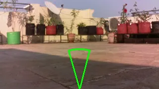
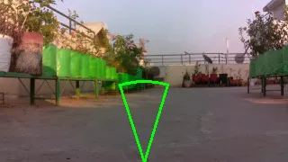
Sample input and processed output images are shown for reference below


The images show original image and the processed image showing the best path. In the processed image, A green cone represents a valid path and a red represents a path that does not satisfy all the conditions.
A sample video of this can be viewed below. The settings for these are
- MinSafeDistanceFactor = 0.5
- MinPathWidthFactor = 0.4
- MinObjectHeightFactor = 0.1
- MinObjectWidthFactor = 0.1
In this implementation, there are a few additional conditions that were put in place to avoid any obstacles. In case the best direction is above 45 degrees from the center, it’s not possible to identify all the obstacles immediately as the field of view is restricted. In such cases, the rover turns to the new direction and waits for a confirmation if the path is obstacle free. If yes, it continues to traverse in the new direction, else, it will rotate and wait for confirmation.
In our next blog, we show how the obstacle avoidance algorithm works at night using IR.